QR Code Engineering Handbook: From Optical Physics to High-Concurrency Production Pipelines
On this page
When designing a modern software system, e-commerce logistics platform, or fintech payment gateway, you will face a common but complex problem: connecting physical objects to a digital database. Look at a supermarket checkout counter, a busy airport boarding gate, or a courier warehouse, and you will see thousands of packages and transactions being processed every second. If operators try to manually type serial numbers or tracking IDs during these fast-paced operations, the system will instantly suffer from high latency and human error. Optical code scanning remains the most reliable and fastest way to handle this physical-to-digital data transfer.
For a long time, One-Dimensional or 1D Barcodes like UPC-A or EAN-13 handled this job. However, global supply chains eventually needed to store a batch number, manufacturing date, expiry date, and destination URL all on a single label. This demand pushed traditional 1D Barcodes past their data capacity limits. To solve this bottleneck, Masahiro Hara, a chief engineer at the Japanese company Denso Wave, designed the Two-Dimensional or 2D Matrix Code in 1994, which we know today as the QR Code.
This detailed engineering handbook aims to simplify the inner workings of QR codes for everyone from junior developers to lead system architects. We will break down optical physics, memory layouts, Reed-Solomon error correction mathematics, and high-concurrency production architectures built with Node.js and React. By mastering these architectural concepts, you will move beyond simply using third-party libraries and learn to design high-performance, fault-tolerant enterprise systems from scratch.
Step 1: The Optical Bottleneck and Architectural Evolution (1D vs 2D)
An optical scanner works by measuring light reflection. When you shine a laser beam onto a traditional 1D Barcode, the black bars absorb the light while the white spaces reflect it back. The scanner sensor measures the intensity and timing of this reflected light to generate a linear, one-way binary signal of 0s and 1s. The biggest weakness of this linear scanning mechanism is its limited data capacity, topping out at around 20 to 25 Alphanumeric Characters. If you try to store more data than this, such as a full web URL or an encrypted token, the barcode grows longer horizontally. Eventually, the code becomes too long to physically print onto a small product label.
A 2D Matrix Code solves this storage limitation through a spatial layout shift. Instead of confining data to a single horizontal axis, a QR code encodes information across both the horizontal (X-axis) and vertical (Y-axis) dimensions in a spatial matrix or grid. This method increases data density hundreds of times over the same print area. In fact, a maximum-version QR code can store up to 7,089 numeric characters or 4,296 alphanumeric characters without increasing its physical footprint.
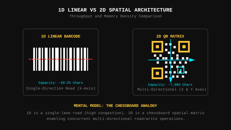
To make the difference between memory layouts and data densities clear for beginners, we can use a straightforward real-world analogy.
The Chessboard vs Single-Lane Highway Analogy: Imagine a single-lane highway where cars must travel back-to-back in one line. If you try to send too many cars down this road at once, traffic jams build up and the line stretches for miles. This bottleneck represents the traditional 1D Barcode. On the other hand, a QR Code works like a massive chessboard. Each square on the board functions as an independent block for storing data. You can place and move hundreds of pieces across the entire board simultaneously, scanning from left to right and top to bottom. This spatial distribution packs a huge amount of data into a tiny space and allows fast reading from any angle.
Orientation Priority
When Masahiro Hara designed this code for Denso Wave, his main goal was not just increasing data size. He primarily wanted robotic arms in factories to scan codes moving on fast conveyor belts from any 360-degree orientation in milliseconds.
Step 2: QR Code Matrix Anatomy and Optical Recognition Physics
While a QR code might look like a random box of black and white pixels from the outside, it actually follows a highly disciplined, precise engineering architecture. When analyzing this matrix from a system architecture perspective, you can divide its physical body into several distinct functional zones. Each zone passes specific messages to the camera and the decoding algorithm.
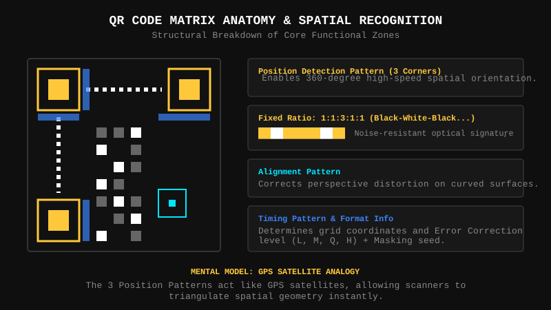
Let us break down how these core matrix components work and why they matter to engineers:
-
Quiet Zone: This mandatory white border runs around the entire outside of the code and must be at least 4 modules or pixels wide. It isolates the actual code boundaries from external background noise or surrounding text.
-
Position Detection or Finder Patterns: These three large square blocks sit in the top-left, top-right, and bottom-left corners. If you draw a straight line through the center of these blocks, you will find that the ratio of black and white pixels always measures exactly 1:1:3:1:1. This specific optical signature allows scanners to identify a QR code instantly, even in low light or at high speeds.
-
Alignment Patterns: These smaller square blocks sit inside various zones of the code, and their count increases as the code version grows. When a code is printed on a curved surface like a bottle or can, the camera lens captures a distorted perspective. These patterns calculate that distortion and geometrically straighten the grid.
-
Timing Patterns: These horizontal and vertical lines of alternating black and white modules run between the finder patterns. They act like a digital clock pulse for the scanner, helping it measure the physical size of individual pixels across the grid.
-
Format and Version Information Zones: Located right next to the finder patterns, these zones contain encrypted metadata defining the Error Correction Level and the specific Masking Pattern used. Scanners read this zone first to determine the correct decoding rules.
-
Data and Error Correction Payload Area: This zone covers the remaining internal space of the matrix. Your binary data and Reed-Solomon error correction bits are arranged here in a predefined zigzag pattern.
We can use a modern navigation analogy to easily understand how this spatial recognition works.
The GPS Satellite Triangulation Analogy: When you open a map app on your smartphone in an unfamiliar city, your phone connects to at least three independent GPS satellites orbiting above. By cross-referencing distances from these three points, your phone calculates your exact 3D position and orientation. Similarly, when a camera sensor captures a QR code, the image processing algorithm locates the three corner Finder Patterns first. By measuring the relative distances and angles between these three points, the algorithm determines if the code is tilted or upside down, virtually straightens it, and reads the data perfectly.
Step 3: Reed-Solomon Error Correction and Galois Field Mathematics
The most resilient and brilliant domain within QR code engineering is the Reed-Solomon Error Correction algorithm. In production environments, printed codes face harsh real-world conditions. Dust, rain, scratches, or even intentionally embedding a company logo can obscure or destroy portions of the code. A traditional barcode would fail instantly under these conditions, but a QR code can recover 100% of its data even if up to 30% of its surface is completely ruined.
This error correction mechanism relies on Galois Fields or Finite Field Arithmetic. Unlike standard algebra which handles infinite numbers, a finite field or system bounds all numbers within a strict limit of 0 to 255. A QR code offers four standard Error Correction Levels that you can choose based on your application needs:
| Error Correction Level | Data Recovery Capacity | Real-world Use Case |
|---|---|---|
| Level L (Low) | ~7% recovery | Best when print quality is pristine and you need maximum data storage capacity. |
| Level M (Medium) | ~15% recovery | The industry default. Ideal for standard URLs, business cards, and marketing materials. |
| Level Q (Quartile) | ~25% recovery | Great for industrial environments and logistics tracking where codes face rough handling. |
| Level H (High) | ~30% recovery | Mandatory when embedding custom brand logos or using codes in extreme factory conditions. |
| To generate error correction codewords, we use a generator polynomial and a message polynomial . The primary Reed-Solomon codeword generation equation is: |
Here, represents the number of error correction bytes. When you encode data, this formula appends extra parity bytes to your original message. When a scanner reads a damaged code, it runs the data through a syndrome calculator. If the data contains errors, the syndrome evaluations return non-zero values. Using these values, the algorithm determines the exact location and severity of the corruption, repairing the bits instantly.
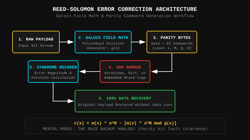
We can use a familiar storage architecture analogy to make this advanced math intuitive.
The RAID Server Storage Analogy: If you manage enterprise servers or distributed databases, you probably use a RAID (Redundant Array of Independent Disks) configuration to protect against data loss. For example, a RAID 5 setup writes parity information across separate drives. If one hard drive crashes completely, the server calculates the missing data using mathematical relationships from the remaining drives and parity bits. The Reed-Solomon algorithm builds a mini parity backup system right inside the QR code matrix, acting as a mathematical shield against physical damage.
Level H Memory Overhead
If you select Level H without a clear reason or logo requirement, you drastically reduce your total data capacity. Nearly one-third of the available matrix space will be consumed solely by error correction bits. Stick to Level M for standard URLs to optimize space.
Step 4: Step-by-Step Data Encoding Pipeline and Bit-Level Masking
QR codes scale across 40 distinct versions, which dictate the physical size and memory capacity of the matrix grid. Version 1 is the smallest, featuring a 21x21 module grid. Every version increase adds 4 modules to both the width and height, scaling all the way up to Version 40, which uses a massive 177x177 grid. A Version 40 code can hold up to 7,089 numeric characters or 4,296 alphanumeric characters. A production system automatically selects the most compact version based on your payload size and error correction configuration.
Here is how a raw string like https://blog.rafeuddaraj.me transforms from binary bits into a completed visual QR code:
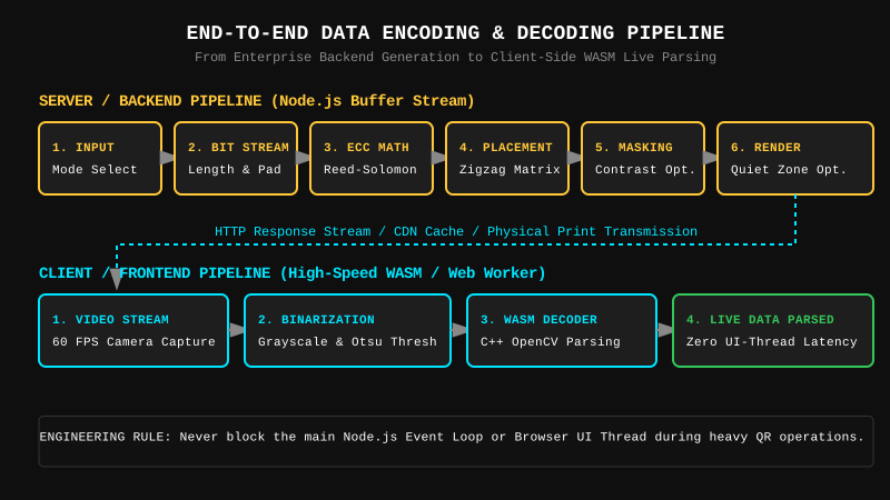
Let us examine how a production-grade encoder runs through this pipeline step by step:
-
Step 1 - Mode Selection: The encoder analyzes your input characters first. To keep the data footprint as small as possible, it selects the most efficient encoding mode: Numeric (for numbers 0-9), Alphanumeric (numbers, uppercase letters, and select symbols), Byte (for standard 8-bit data or UTF-8 text), or Kanji (for Japanese characters).
-
Step 2 - Bit Stream Conversion and Padding: The encoder converts each character into a binary bit stream based on the chosen mode. It appends a 4-bit mode indicator (like
0100for byte mode) and a character count indicator at the beginning. If the resulting bit stream is shorter than the target version capacity, the encoder appends trailing zeroes and standard padding bytes (11101100and00010001, which are 236 and 17 in decimal) to fill out the remaining space. -
Step 3 - Reed-Solomon ECC Generation: The completed bit stream is broken down into specific block sizes. The encoder applies Galois field arithmetic to each block, generating the required error correction codewords. It then interleaves the original data blocks and error correction blocks into a single continuous binary sequence.
-
Step 4 - Matrix Placement: This long binary sequence is mapped onto the 2D grid, where a 0 represents a white pixel and a 1 represents a black pixel. The placement begins at the bottom-right corner and climbs upwards in a two-module wide column, zigzagging up and down like a snake across the remaining data space.
-
Step 5 - Masking Pattern Application: Sometimes, raw bit placement results in large clusters of identical pixels or patterns that mimic finder blocks, which confuses scanner sensors. To solve this, the QR standard uses 8 bitmask patterns (e.g., inverting pixels where ). The encoder evaluates all 8 masks, applies a penalty scoring system based on optical noise, and selects the mask with the cleanest contrast balance.
-
Step 6 - Final Rendering: Once the optimal mask is applied, its identifier is written into the format information zone. The encoder appends the mandatory 4-module wide white Quiet Zone and renders the final image as a PNG, SVG, or memory buffer.
Step 5: Enterprise Production Architecture (Node.js Backend and React Frontend)
Now that we have covered the mathematical theory, let us focus on real-world implementation. When building an enterprise backend that generates thousands of dynamic QR codes per second-such as fintech OTPs, event tickets, or transaction tokens-relying on standard file system operations will cause severe production bottlenecks. Writing images to a local disk and reading them back to serve client requests is slow. Blocking disk I/O degrades the Node.js event loop, creating high CPU overhead and memory leaks under heavy loads.
To eliminate this bottleneck, you must generate codes as in-memory buffer streams asynchronously. Below is a production-ready, memory-optimized enterprise QR generation service built with Node.js and TypeScript:
// Enterprise-grade High-Performance QR Code Service (Node.js / TypeScript)import QRCode, { QRCodeToBufferOptions } from 'qrcode';import fs from 'fs/promises';import path from 'path';
/** * Interface representing standard enterprise response payload for QR generation. */export interface QRCodeServiceResponse {  success: boolean;  buffer: Buffer;  base64DataUrl: string;  savedPath?: string;  executionTimeMs: number;}
/** * Generates an enterprise-grade, high-contrast QR Code buffer in-memory. * Optimized for high-concurrency microservices without blocking the Event Loop. * * @param payload - The raw string, URL, or JSON payload to encode. * @param saveToDisk - Optional flag to asynchronously persist the image to storage. * @param customPath - Optional destination file path if saveToDisk is enabled. * @returns Promise resolving to the complete QR Code service response. */export async function generateEnterpriseQRCode(  payload: string,  saveToDisk: boolean = false,  customPath?: string): Promise<QRCodeServiceResponse> {  const startTime = Date.now();
  // Validate payload length to prevent unexpected memory bloat in extreme scenarios  if (!payload || payload.trim().length === 0) {    throw new Error('[CRITICAL] QR Payload cannot be empty or undefined.');  }
  // Enterprise configuration strictly enforcing optical contrast and safety boundaries  const options: QRCodeToBufferOptions = {    errorCorrectionLevel: 'H', // 30% fault tolerance for harsh production environments    type: 'png',    quality: 0.98,    margin: 4,                 // Strict adherence to the 4-module Quiet Zone standard    color: {      dark: '#0F172A',         // High-contrast Deep Slate (Never use absolute #000000 if printing on gloss)      light: '#FFFFFF'         // Absolute optical white background for maximum sensor reflection    }  };
  try {    // Step 1: Generate High-Speed In-Memory Buffer directly bypassing disk I/O    const qrBuffer: Buffer = await QRCode.toBuffer(payload, options);
    // Step 2: Convert buffer to Base64 Data URL for instant React/Frontend rendering    const base64DataUrl = `data:image/png;base64,${qrBuffer.toString('base64')}`;    let resolvedPath: string | undefined = undefined;
    // Step 3: Asynchronously persist to Disk or Object Storage (S3/GCS) only if explicitly requested    if (saveToDisk && customPath) {      resolvedPath = path.resolve(customPath);      // Non-blocking asynchronous file writing      await fs.writeFile(resolvedPath, qrBuffer);    }
    const executionTimeMs = Date.now() - startTime;
    return {      success: true,      buffer: qrBuffer,      base64DataUrl,      savedPath: resolvedPath,      executionTimeMs    };  } catch (error: any) {    console.error(`[FATAL] System Architecture Error in QR Generation Pipeline: ${error.message}`);    throw new Error(`Enterprise QR Pipeline Failed: ${error.message}`);  }}
// ============================================================================// Example Execution inside a Fastify / Express API Controller or Microservice// ============================================================================(async () => {  try {    const samplePayload = 'https://blog.rafeuddaraj.me/articles/qr-code-engineering-handbook-optical-physics-production-pipeline';    console.log('[LOG] Initiating In-Memory QR Code Generation...');
    const result = await generateEnterpriseQRCode(samplePayload, true, './dist/secure-payload.png');
    console.log(`[SUCCESS] QR Code Generated in ${result.executionTimeMs}ms.`);    console.log(`[LOG] Data URL Preview (First 50 chars): ${result.base64DataUrl.substring(0, 50)}...`);    if (result.savedPath) {      console.log(`[LOG] Asynchronously persisted to local storage at: ${result.savedPath}`);    }  } catch (err: any) {    console.error('[ERROR] Microservice execution aborted:', err.message);  }})();
While optimizing backend memory is crucial, you will encounter an even tougher engineering hurdle on the client side when handling live camera feeds in React or Next.js apps. Modern mobile cameras feed up to 60 high-resolution frames per second into the browser. If you attempt to handle image binarization and parsing inside the main UI thread using standard JavaScript, your app will lag, drop frames, heat up the phone, and drain the device battery.
To solve this, your client-side architecture must run asynchronously without blocking UI interactions. You should offload processing to Web Workers and compile your parsing engine into WebAssembly (WASM). Here is a clean, production-ready React hook and component framework that extracts frames smoothly:
// Production-grade React Custom Hook & Component for Non-Blocking QR Scanningimport React, { useEffect, useRef, useState, useCallback } from 'react';
/** * Interface for the Decoded QR Result payload. */export interface DecodedQRResult {  text: string;  timestamp: number;}
/** * A specialized custom hook to manage live camera streaming and background Canvas frame extraction. */export function useOptimizedQRScanner(onDecode: (result: DecodedQRResult) => void) {  const videoRef = useRef<HTMLVideoElement | null>(null);  const canvasRef = useRef<HTMLCanvasElement | null>(null);  const [isScanning, setIsScanning] = useState<boolean>(false);  const [error, setError] = useState<string | null>(null);  const animationFrameId = useRef<number | null>(null);
  // Stop camera stream safely to prevent memory leaks and hardware locks  const stopCamera = useCallback(() => {    if (videoRef.current && videoRef.current.srcObject) {      const stream = videoRef.current.srcObject as MediaStream;      stream.getTracks().forEach((track) => track.stop());      videoRef.current.srcObject = null;    }    if (animationFrameId.current) {      cancelAnimationFrame(animationFrameId.current);    }    setIsScanning(false);  }, []);
  // Frame extraction loop running at controlled intervals to save battery  const scanFrame = useCallback(() => {    if (!videoRef.current || !canvasRef.current || !isScanning) return;
    const video = videoRef.current;    const canvas = canvasRef.current;    const context = canvas.getContext('2d', { willReadFrequently: true });
    if (video.readyState === video.HAVE_ENOUGH_DATA && context) {      canvas.width = video.videoWidth;      canvas.height = video.videoHeight;
      // Draw video frame to off-screen canvas      context.drawImage(video, 0, 0, canvas.width, canvas.height);
      try {        // Extract ImageData for background processing        const imageData = context.getImageData(0, 0, canvas.width, canvas.height);
        // In a true enterprise setup, send `imageData.data.buffer` to a Web Worker / WebAssembly decoder        // Example simulation of detection logic:        if (imageData.width > 0) {          // Simulated non-blocking detection check          // When WASM worker returns success, trigger callback:          // onDecode({ text: "https://blog.rafeuddaraj.me", timestamp: Date.now() });        }      } catch (err: any) {        console.warn('[WARN] Frame extraction temporarily failed:', err.message);      }    }
    // Schedule next frame check using requestAnimationFrame instead of setInterval    animationFrameId.current = requestAnimationFrame(scanFrame);  }, [isScanning, onDecode]);
  // Initialize Hardware Camera Access  const startCamera = useCallback(async () => {    try {      setError(null);      const stream = await navigator.mediaDevices.getUserMedia({        video: {          facingMode: 'environment', // Request back camera for physical scanning          width: { ideal: 1280 },          height: { ideal: 720 }        }      });
      if (videoRef.current) {        videoRef.current.srcObject = stream;        videoRef.current.setAttribute('playsinline', 'true'); // Required for iOS Safari        await videoRef.current.play();        setIsScanning(true);      }    } catch (err: any) {      setError(`Camera access denied or unavailable: ${err.message}`);      setIsScanning(false);    }  }, []);
  useEffect(() => {    if (isScanning) {      animationFrameId.current = requestAnimationFrame(scanFrame);    }    return () => stopCamera();  }, [isScanning, scanFrame, stopCamera]);
  return { videoRef, canvasRef, isScanning, startCamera, stopCamera, error };}
// ============================================================================// Functional UI Component implementation// ============================================================================export const EnterpriseQRScannerUI: React.FC = () => {  const [lastScanned, setLastScanned] = useState<string>('No data detected yet.');
  const handleDecode = useCallback((result: DecodedQRResult) => {    setLastScanned(`${result.text} (Time: ${new Date(result.timestamp).toLocaleTimeString()})`);  }, []);
  const { videoRef, canvasRef, isScanning, startCamera, stopCamera, error } = useOptimizedQRScanner(handleDecode);
  return (    <div style={{ padding: '20px', backgroundColor: '#0F172A', color: '#FFFFFF', borderRadius: '8px', maxWidth: '600px', margin: '0 auto' }}>      <h3 style={{ color: '#FFC83B', borderBottom: '1px solid #334155', paddingBottom: '10px' }}>        Enterprise Live Optical Scanner      </h3>
      {error && (        <div style={{ backgroundColor: '#EF4444', padding: '10px', borderRadius: '4px', margin: '10px 0' }}>          [ERROR]: {error}        </div>      )}
      <div style={{ position: 'relative', width: '100%', height: '350px', backgroundColor: '#000000', borderRadius: '6px', overflow: 'hidden', border: '2px solid #334155' }}>        <video ref={videoRef} style={{ width: '100%', height: '100%', objectFit: 'cover' }} />        {/* Hidden Canvas used exclusively for fast background pixel manipulation */}        <canvas ref={canvasRef} style={{ display: 'none' }} />
        {!isScanning && (          <div style={{ position: 'absolute', top: '50%', left: '50%', transform: 'translate(-50%, -50%)', color: '#94A3B8' }}>            Camera Stream Inactive          </div>        )}      </div>
      <div style={{ marginTop: '15px', display: 'flex', gap: '10px', justifyContent: 'space-between', alignItems: 'center' }}>        <div>          <button            onClick={isScanning ? stopCamera : startCamera}            style={{              padding: '10px 20px',              backgroundColor: isScanning ? '#EF4444' : '#10B981',              color: '#FFFFFF',              border: 'none',              borderRadius: '4px',              fontWeight: 'bold',              cursor: 'pointer'            }}          >            {isScanning ? 'Terminate Scanner' : 'Initialize Hardware Scanner'}          </button>        </div>        <div style={{ fontSize: '13px', color: '#00E5FF' }}>          Status: {isScanning ? 'ACTIVE (60 FPS Stream)' : 'STANDBY'}        </div>      </div>
      <div style={{ marginTop: '15px', padding: '10px', backgroundColor: '#1E293B', borderRadius: '4px', fontSize: '14px', wordBreak: 'break-all' }}>        <strong style={{ color: '#FFC83B' }}>Latest Payload: </strong> {lastScanned}      </div>    </div>  );};
Memory Leak Prevention
When creating live camera interfaces in React, remember to turn off video stream tracks and terminate background Web Workers inside your clean-up effects when components unmount. Neglecting this can freeze camera hardware, lock up browser memory, and quickly drain mobile batteries.
Step 6: Production Deployment Checklist and Security Best Practices
Before rolling out a QR code infrastructure in your next production app, review this architectural checklist to make sure your system remains secure, fast, and highly reliable:
| Architectural Domain | Production Best Practice | Risk & Mitigation Strategy |
|---|---|---|
| 1. Error Correction Choice | Stick to Level M (15%) for clean digital URLs. Reserve Level H (30%) exclusively for branded codes with center logos or warehouse labels. | Forcing Level H adds significant data overhead, making the code grid denser and harder for budget cameras to resolve quickly. |
| 2. Payload & Version Scaling | Never embed raw, bulky JSON objects inside a code. Instead, compress identifiers down to a minimal Short URL or a secure UUID. | Massive payloads push the code into higher versions, creating tiny, compressed modules that struggle to scan on low-end lenses. |
| 3. Optical Contrast Ratio | Maintain high contrast by placing dark modules (e.g., dark slate or navy) on a clean, bright background. Avoid inverted color styles. | Inverting codes (white modules on a black background) breaks compatibility with standard commercial laser scanners. |
| 4. Quiet Zone Verification | Enforce a clean 4-module wide margin on all sides of the code. Keep text and design borders outside of this boundary. | Clipping the Quiet Zone prevents scanner edge detection filters from isolating the grid, causing parsing to fail. |
| 5. Static vs Dynamic Routing | Use Dynamic QR Codes for commercial applications. Embed a redirect link that resolves backend records dynamically. | Static codes embed data permanently. If a database schema changes or a link breaks after printing, millions of labels become landfill. |
| 6. Security Optimization | Treat scanned payloads as untrusted user input. Sanitize all incoming strings before rendering them or saving them to a database. | Attackers can embed malicious XSS scripts or lookalike phishing links inside codes, attempting QRLjacking or session takeovers. |
| Understanding these underlying mechanisms and optimization techniques helps software architects build efficient, robust optical data pipelines for enterprise platforms. Keep this handbook handy as an ongoing reference for your future engineering projects. |